

Bargain Cave ~ Huge Discount Offer!
The bargain cave is a collection of clearance and discounted items.
SKU : MSR601575
In Stock Quantity:0
Couldn't load pickup availability
![]()
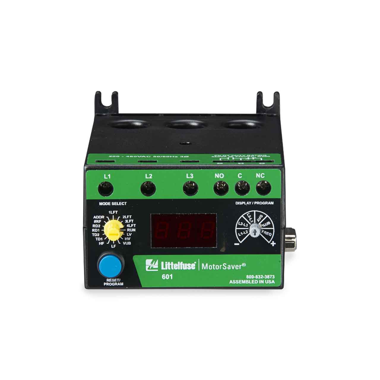
The model 601 is a fully-programmable voltage monitor designed to protect 3-phase motors from loss of any phase (single-phasing), phase reversal, low or high voltage, voltage unbalance, low or high frequency, and rapid cycling. It can be used as a stand-alone product or networked with an RM1000, RM2000, PLC, computer or SCADA system.
When a harmful condition is detected, the 601’s output relay is deactivated after the specified trip delay. The output relay reactivates after power line conditions return to an acceptable level for the programmed restart delay (RD2)
Eleven (11) parameters can be viewed from the three digit LED
display or from a networked device:
•Low Voltage •High Voltage •Voltage Unbalance •Low Frequency •High Frequency •Trip Delay for Voltage/Frequency Faults, •Trip Delay for Single-Phase Faults, •Rapid Cycle Timer (RD1), •Restart Delay After all Faults (RD2) •Type of Restart After all Faults (Manual or Automatic).
Six parameters can be viewed as the motor is running:
•L1-L2 Voltage •L2-L3 Voltage •L1-L3 Voltage •Average Voltage •Voltage
Unbalance(%) •Voltage Frequency (%).
When used with the RS485MS-2W communications module, the 601 can communicate with most Modbus RTU master devices. Voltage conditions can be monitored and setpoints can be changed remotely using Solutions software, an RM1000, RM2000 or other device.
Three-Phase Line Voltage . . . . . . . . . . . . 500-600 VAC
Frequency . . . . . . . . . . . . . . . . . . . . . 50 or 60 Hz
Programmable Operating Points
TD1 - Trip Delay for Voltage/Unbalance/Frequency Faults . . . . . . . . . . . . . . 1-50 seconds
TD2 - Trip Delay for Single-Phase Faults . . . . . . . . . . . . . . 1-50 seconds
RD1 - Rapid Cycle Timer . . . . . . . . . . . . . . . . . . . . . 0, 2-500 seconds
RD2 - Restart Delay After All Faults . . . . . . . . . . . . 2-500 seconds
#RF-Type of Restart . . . . . . . . . . . . Manual or Automatic
ADDR-RS-485 Address . . . . . . . . . . . . A01-A99
Fixed Reset Points
Output Contact Rating . . . . . . . . . . . . . . . . . . . . . 480VA @ 240VAC Pilot Duty
Temperature Range . . . . . . . . . . . . . . . . . . . . . -20° to 70°C (-4° to 158°F)
Accuracy
Repeatability
Safety Marks
Weight . . . . . . . . . . . . . . . . . . . . . . . . 19.2 oz.
Mounting Method . . . . . . . . . . . Surface mount (4 - #8 screws) or DIN rail mount
*The 601 can be preprogrammed prior to installation by applying at least 120V to the L1 and L2 terminals.
*575V Model
![]() WARNING: Cancer and Reproductive Harm - www.P65Warnings.ca.gov
WARNING: Cancer and Reproductive Harm - www.P65Warnings.ca.gov

Littelfuse 601575 Product Specifications

Dedicated to deliver the highest quality products, and services in the water and wastewater industry, and with the help of our well-trained staff, provide a lasting value to each customer we support... read more
As time-tested specialists in water and waste water pumping systems, we are your best choice for pumps and related equipment.


The bargain cave is a collection of clearance and discounted items.